
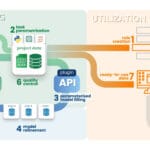
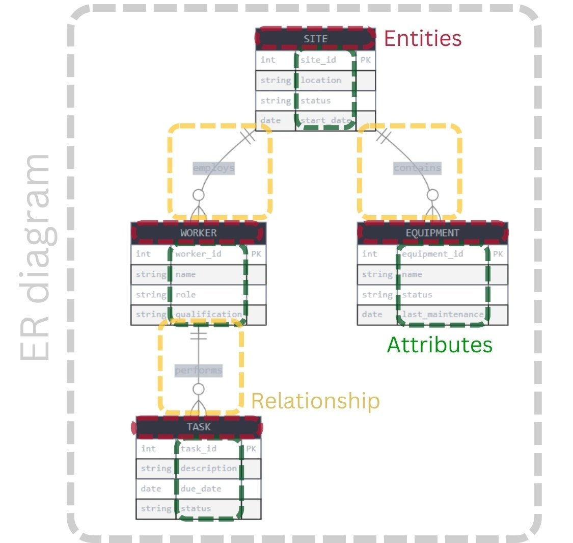
No construction project in the world has ever started in a CAD program. Before a drawing or model takes shape in CAD, it passes through the conceptualization stage (Fig. 6.4-1, stages 1-2), where the focus is on the parameters that define the basic idea and logic of the future object. This stage corresponds to the conceptual level in data modeling (Fig. 4.3-6). Parameters may exist solely in the designer’s mind, but ideally they are formalized in the form of structured lists, tables or stored in databases (Fig. 6.4-3), which allows for transparency, reproducibility and further automation of the design process.

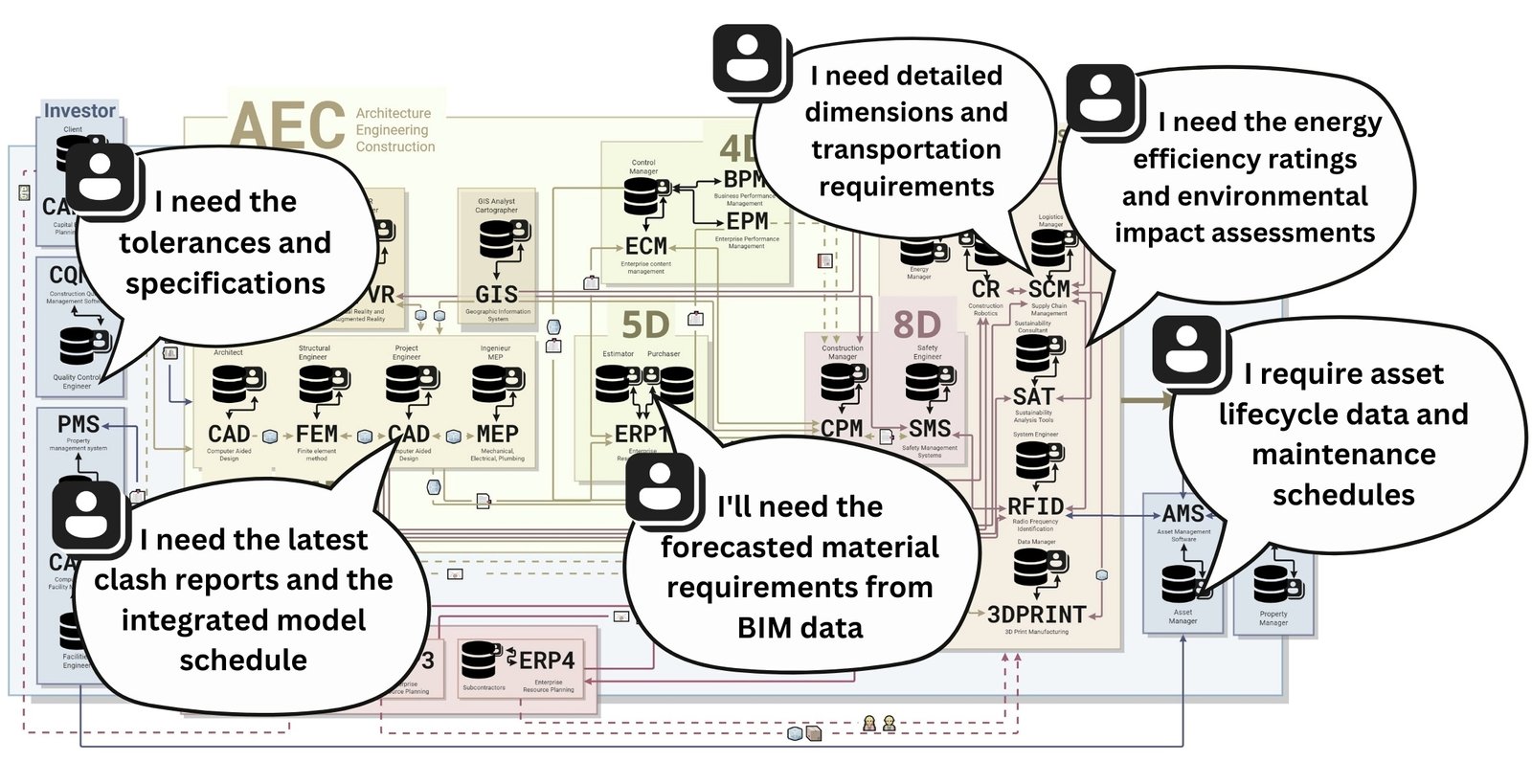
Before starting the CAD modeling itself (the logical and physical phase of data modeling (Fig. 4.3-7)), it is important to define the boundary parameters that serve as the basis of the project. These attributes, as with other requirements, are collected from the very end of the data usage chain (e.g. systems) and through them the constraints, goals and key characteristics of future objects in the project are already defined.
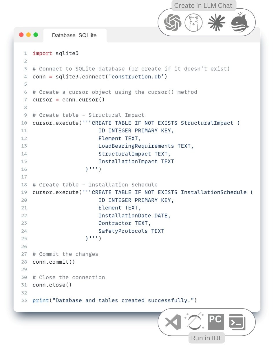
The modeling itself can be fully automated by 60-100% with the help of parametric modeling tools (Fig. 6.4-3), if the requirements are well defined. As soon as the project is described in the form of parameters, its formation becomes technically feasible with the help of visual programming languages such as Grasshopper Dynamo, embedded in modern CAD -environments or free solutions in Blender, UE, Omniverse.

Already today, large industrial and typified projects are not created by the hands of the design department, but through parametric tools and visual programming. This makes it possible to build a model based on data rather than on the subjective decisions of a particular designer or manager.
Content precedes design. Design without content is not design, but decoration (“Jeffrey Zeldman Presents,” May 6, 2008).
– Jeffrey Zeldman, web designer and entrepreneur
The process does not start with drawing or 3D -modeling, but with the formation of requirements. It is the requirements that determine what elements will be used in the project, what data needs to be transferred to other departments and systems. Only the existence of structured requirements makes it possible to automatically check models on a regular basis (for example, even every 10 minutes without distracting the designer from his work).
Perhaps in the future CAD- (BIM-) system will become just an interface for filling the database, and in what CAD tool is modeling (physical level) – will not matter.
Similarly, in mechanical engineering, 3D modeling is often used but is not a necessary or mandatory element of the project. In most cases, the classic 2D documentation is sufficient and the necessary information model is created on its basis. This model is assembled from components structured according to industry standards and contains all the necessary information for understanding the design and organization of production. The factory information model is then used to create a factory information model, to which specific products and flow charts, already oriented to the needs of technologists, are added. The whole process can be organized without unnecessary complexity, without overloading the system with 3D graphics where they do not provide real advantages.
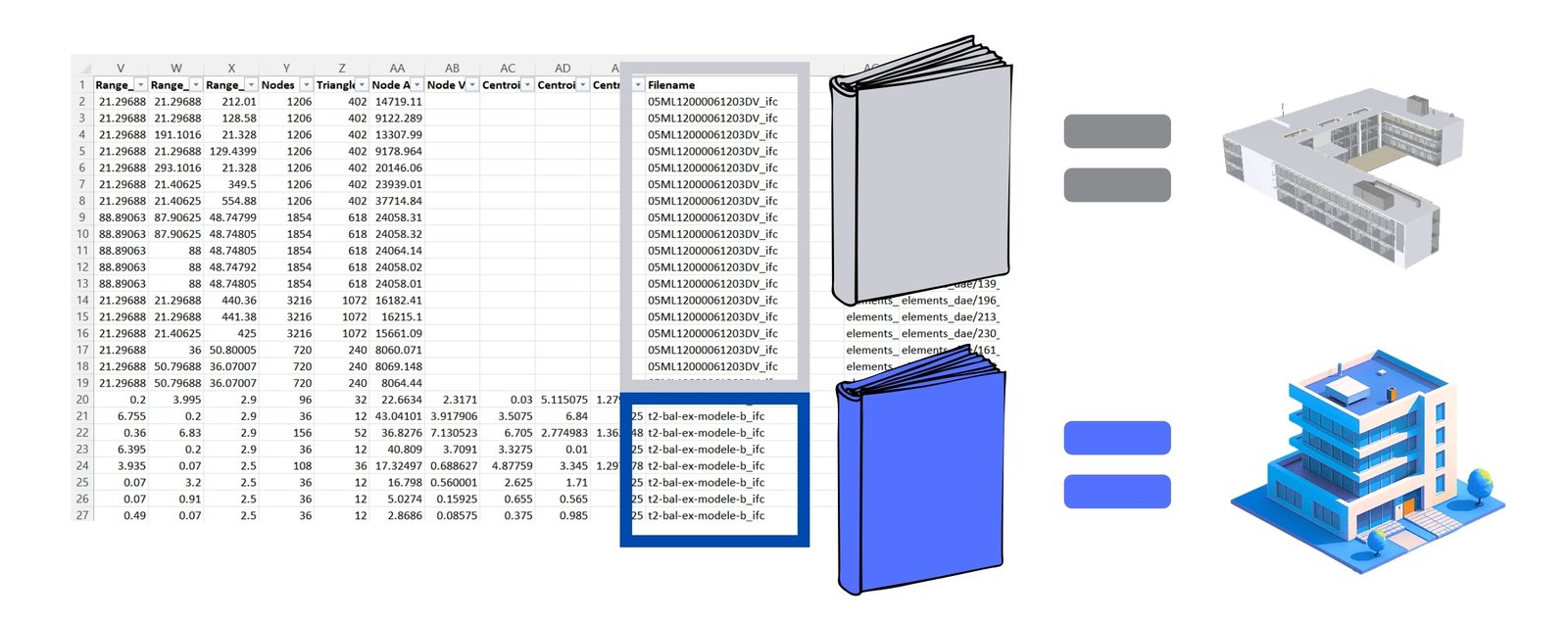
It is important to realize that the 3D model itself and CAD -system should not play the main role – it is just a tool for quantitative and geometric analysis. All other parameters, except geometry, which describe the entity, should be stored and processed outside the CAD environment (BIM) if possible.
Design through parameters is not just a trend, but the inevitable future of the construction industry. Instead of creating complex 3D -models manually, designers will work with data, validate it and automate processes, bringing construction closer to the world of programming. Over time, design processes will be built on the principles of software development:
- Create requirements → Create model→ Upload to server→ Validate changes→ Pull request
- The Pull request automatically runs model checks against requirements that were created before or during the design process
- After data quality checks and approval, changes are implemented into the project, the common database or transferred automatically to other systems
Already now in mechanical engineering, such design changes start with the formation of a change notice. A similar scheme awaits the construction industry: design will be an iterative process where each step is supported by parametric requirements. Such a system will allow designers to create automated checks and automated pull request for specific requirements.
The designer of the future is primarily a data operator, not a manual modeler. His task is to fill the project with parametric entities, where geometry is only one of the attributes.
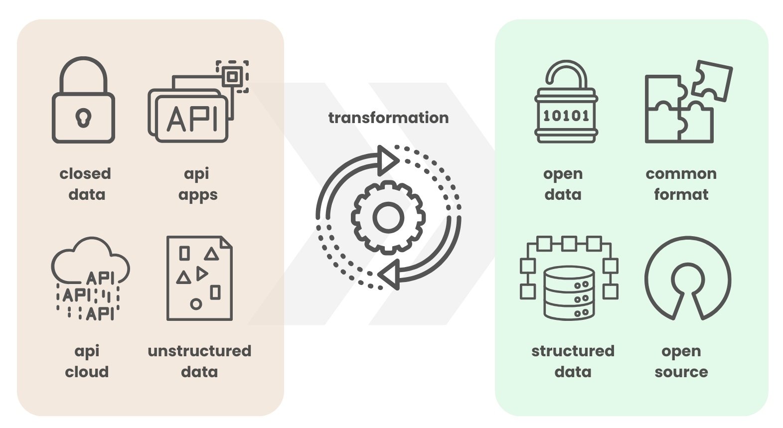
It is the understanding of the importance of data modeling, classification and standardization, which have been discussed in detail in the previous chapters of the book, that will play an important role in the transformation. The design regulations of the future will be formalized as key-value parameter pairs in the form of XLSX or XML -schemas.
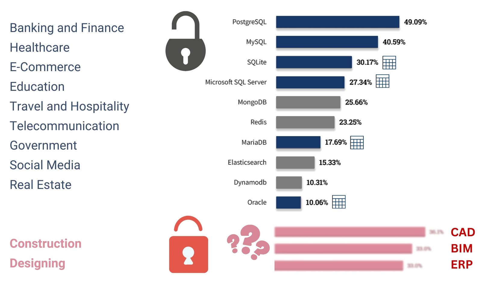
The future of the construction industry is about collecting data, analyzing it, validating it and automating processes with analytics tools. BIM (or CAD) is not the end goal, but only a stage of evolution. When professionals realize that they can work directly with data, bypassing traditional CAD tools, the term “BIM” itself will gradually give way to the concepts of using structured and granular construction project data.
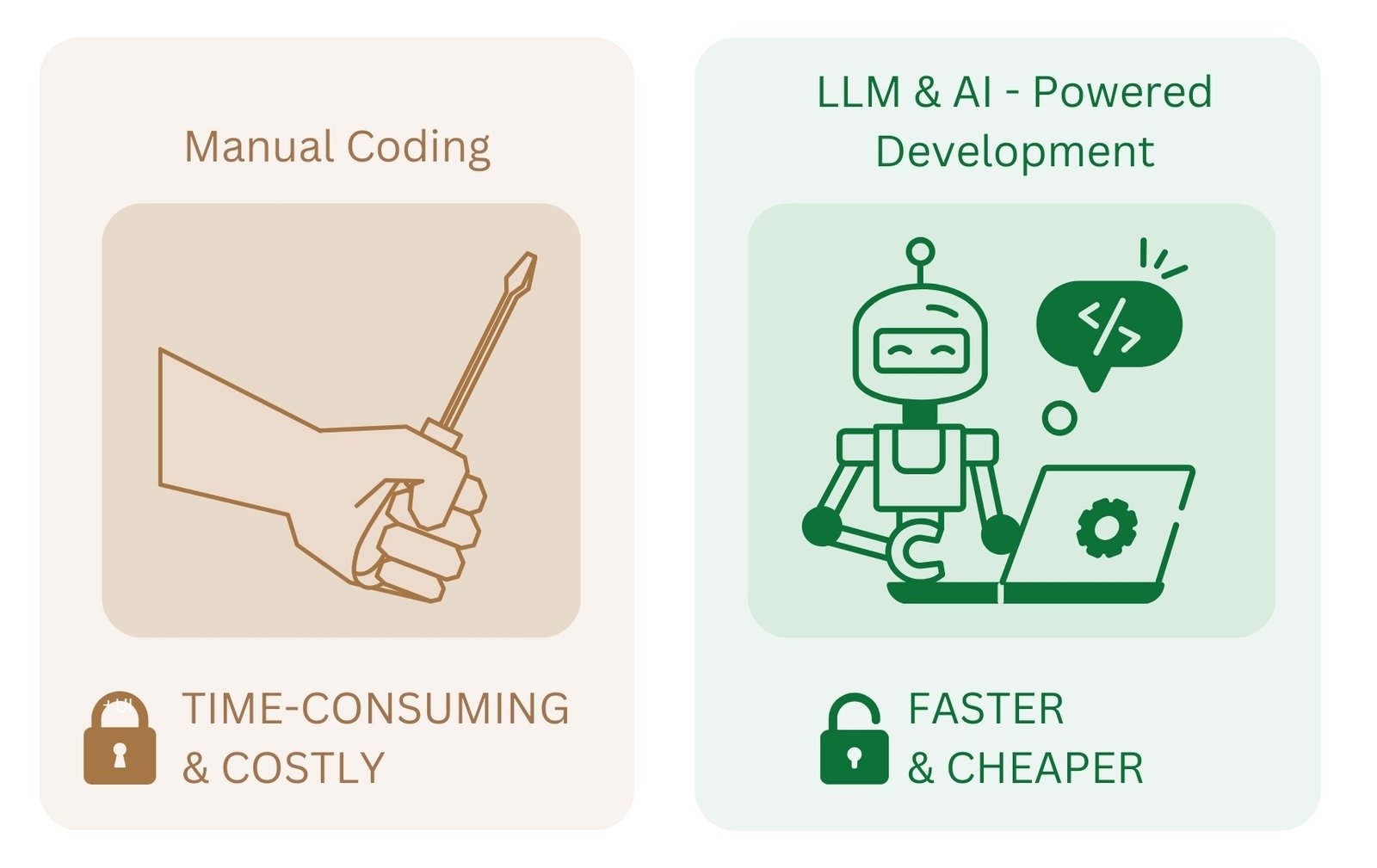
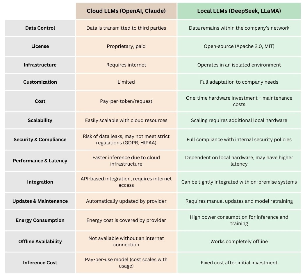
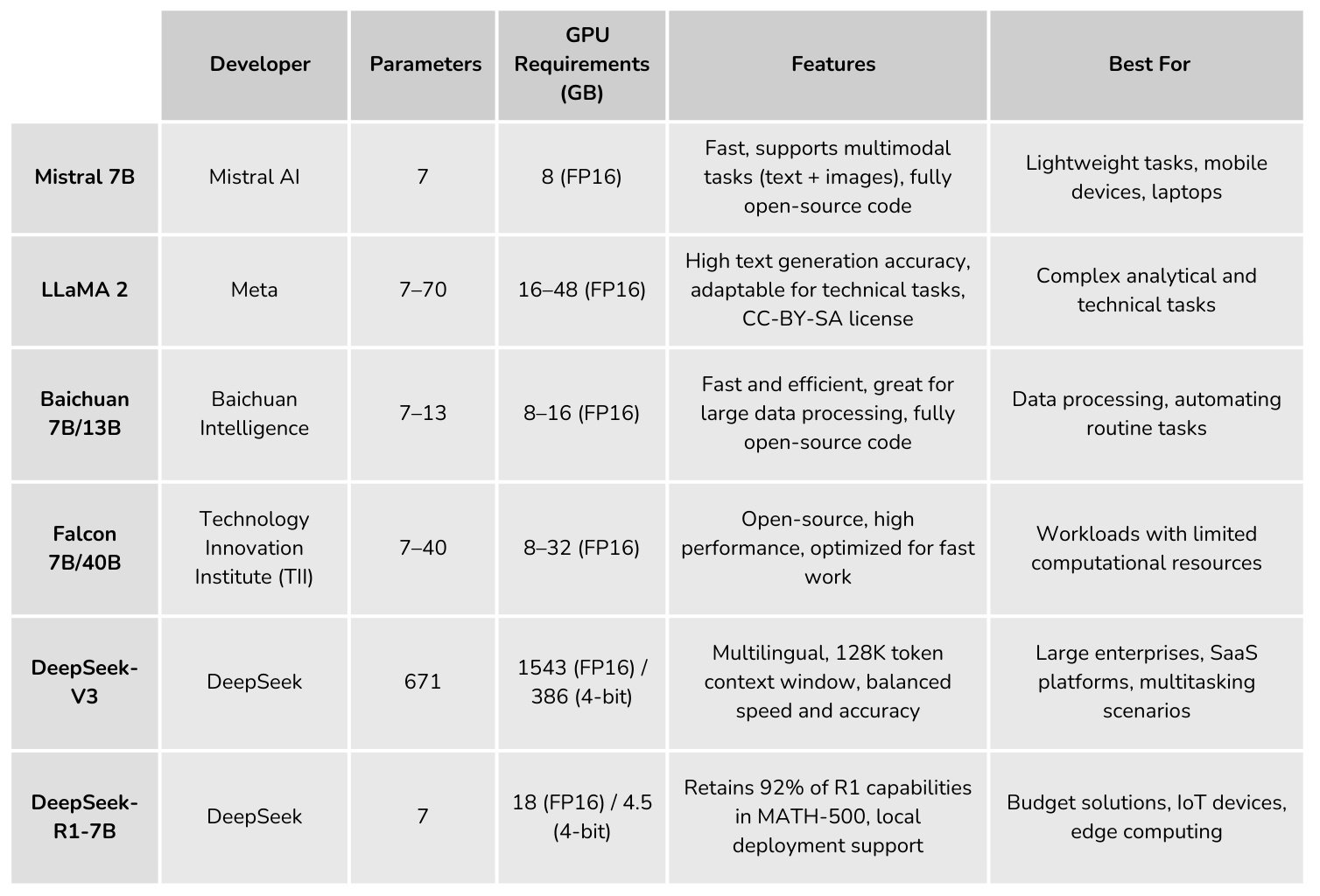
One of the key factors accelerating the transformation has been the emergence of large language models (LLM) and the tools based on them. These technologies are changing the way design data is handled, enabling access to information without the need for in-depth knowledge of APIs or vendor solutions. With LLMs, the process of creating a requirement and interacting with CAD data becomes intuitive and accessible.


