
The process of data processing from DWG -files due to the unstructured nature of the information – has always been a complex task, requiring specialized software and often manual analysis. However, with the development of artificial intelligence and LLM tools, it has become possible to automate many stages of this, today, mostly manual process. Consider a real Pipeline of requests to LLM (in this example ChatGPT) to work with DWG drawings, which allow you to work with the project:
- Filter DWG data by layer, ID and coordinates
- Visualize the geometry of the elements
- Automatically annotate drawings based on parameters
- Expand wall polylines to the horizontal plane
- Create interactive 3D -visualizations of planar data
- Structure and analyze construction data without complex CAD -tools
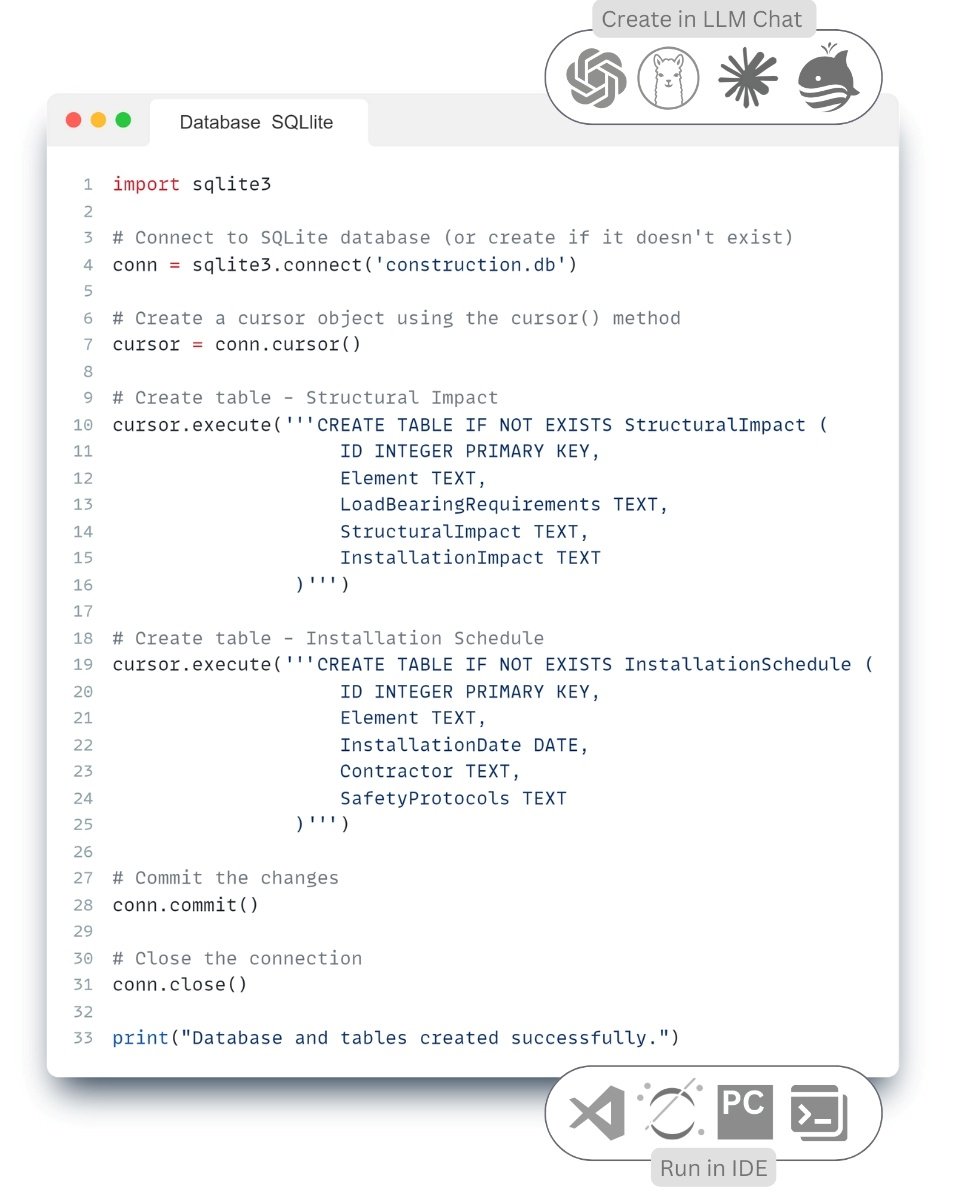
In our case, the process of building Pipeline starts with sequential code generation through the LLM. First, a query describing the task is generated. ChatGPT generates Python -code, which is executed and analyzed, showing the result inside the chat room. If the result is not as expected, the request is corrected and the process is repeated
Pipeline is a sequence of automated steps performed to process and analyze data. In such a process, each step takes data as input, performs transformations, and passes the result to the next step.
After obtaining the desired result, the code is copied from LLM and pasted into the code in the form of blocks in any of the convenient IDEs, in our case on the Kaggle platform.com. The resulting code fragments are combined into a single Pipeline, which automates the entire process – from data loading to its final analysis. This approach allows rapid development and scaling of analytical processes without deep programming expertise. The full code of all the fragments below, along with sample queries, can be found on the Kaggle.com platform by searching for “DWG Analyse with ChatGPT | DataDrivenConstruction” (А. Boiko, “DWG Analyse with ChatGPT | DataDrivenConstruction,” 5 Mar 2024).
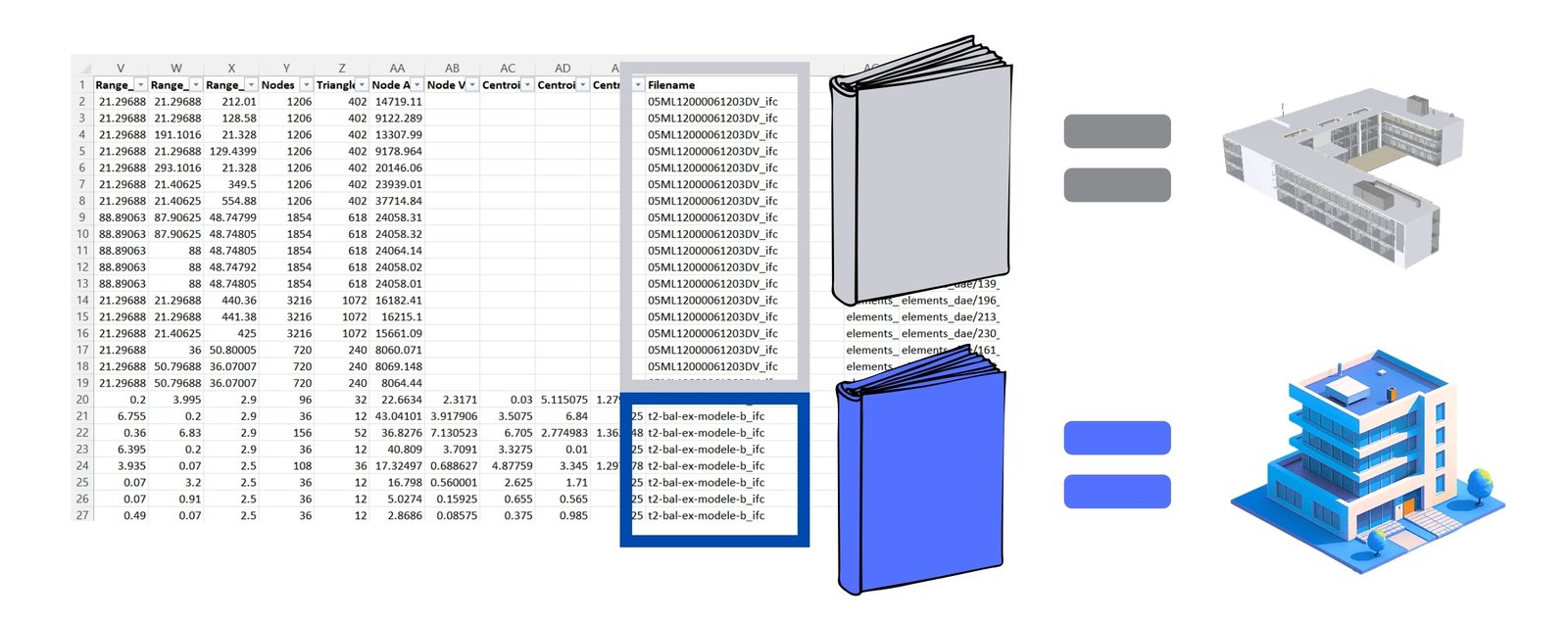
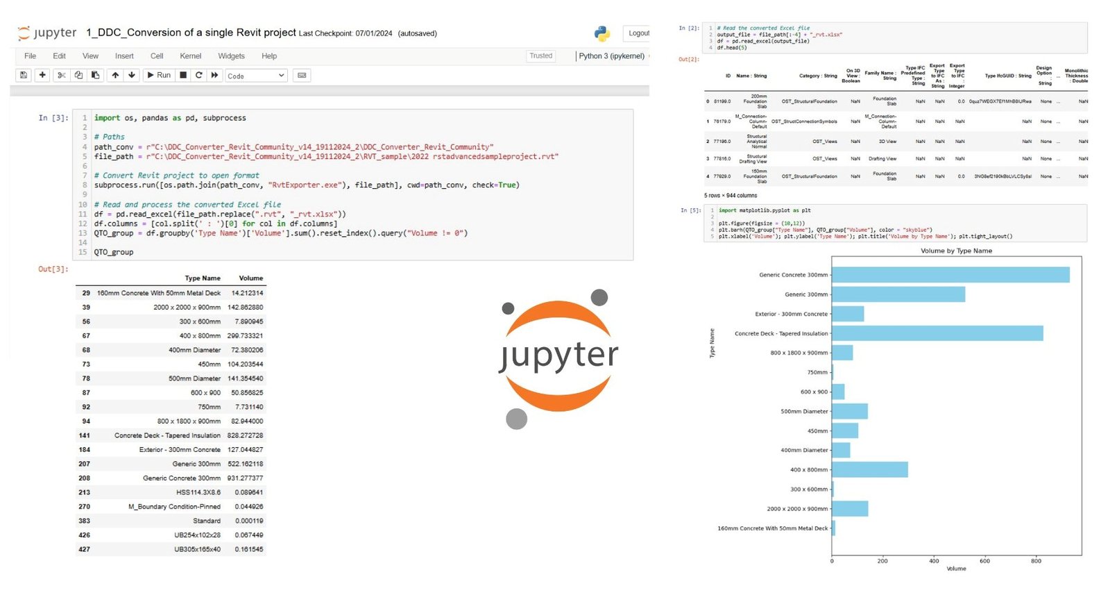
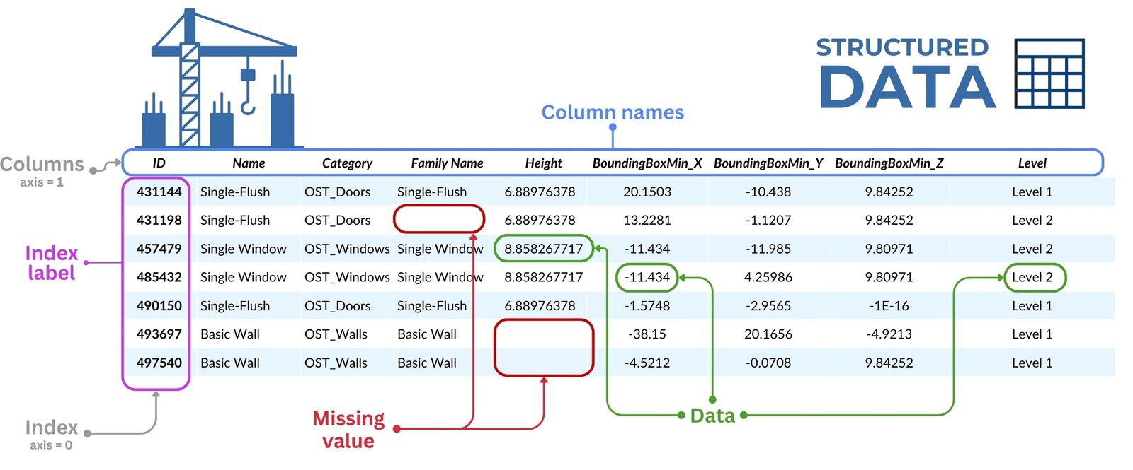
Let’s start the process of working with DWG data, after conversion to structured view (Fig. 4.1-13), with a classical step – grouping and filtering of all the drawing data, necessary for our task wall elements, specifically polylines (parameter ‘ParentID’ allows to group lines into groups), which in the parameter (dataframe column) “Layer” has a string value containing the following combination of letters (RegEx) – “wall”.
- To get the code for a similar task and the result in the form of a picture you should write the following query in LLM:
First, check if the dataframe obtained from DWG contains the defined columns: ‘Layer’, ‘ID’, ‘ParentID’ and ‘Point’. Then filter out the IDs from the ‘Layer’ column that contain the string ‘wall’. Find the items in the ‘ParentID’ column that match these identifiers. Define a function to clean and split the data in the ‘Point’ column. This includes removing brackets and splitting the values into ‘x’, ‘y’ and ‘z’ coordinates. Plot the data using matplotlib. For each unique ‘ParentID’, draw a separate polyline connecting the ‘Point’ coordinates. Make sure the first and last points are connected if possible. Set the appropriate labels and headers, ensuring that the x and y axes are equally scaled.
- The answer LLM will give you a ready-made picture behind which hides the Python code that generated it:

- Now let’s add to the lines the area parameter that each polyline has in its properties (in one of the dataframe columns):
Now get just one “ParentID” from each polyline – find that ID in the “ID” column, take the “Area” value, divide by 1,000,000 and add that value to the graph
 |
- Then we will transform each polyline into a horizontal line, add a parallel line at a height of 3000 mm and connect them into a single plane, to show in this way the layout of the surfaces of the wall elements:
You need to take all the elements from the “Layer” column with the value “wall”. Take these IDs as a list from the “ID” column and find these IDs from the whole dataframe in the “ParentID” column. All elements are lines that are combined into a single polyline. Each line has a different x, y geometry of the first point in the “Point” column. You must take each polyline in turn and from the point 0,0 horizontally draw the length of each segment from the polyline. the length of each segment of the polyline into one line. Then draw exactly the same lines only 3000 higher, connect all points into one plane.
- Now let’s move from 2D projection to 3D -model of walls from flat lines by connecting upper and lower layers of polylines:
Visualize wall elements in 3D, connecting polylines at heights z = 0 and z = 3000 mm. To create a closed geometry representing the walls of the building. Use Matplotlib 3D graphing tool.
 |

To build a logical and reproducible Pipeline – from initial conversion and loading of DWG -file to the final result – it is recommended to copy the generated LLM -block of code to the IDE after each step. In this way, you not only check the result in chat, but also run it in your development environment immediately. This allows you to build the process sequentially, debugging and adapting it as needed.
You can find the complete Pipeline code of all fragments (Fig. 6.4-8 to Fig. 6.4-11) along with sample queries on the Kaggle platform.com by searching for “DWG Analyze with ChatGPT | DataDrivenConstruction” (А. Boiko, “DWG Analyse with ChatGPT | DataDrivenConstruction,” 5 Mar 2024).On Kaggle you can not only view the code and the prompts used, but also copy and test the entire Pipeline with the original DWG dataframes in the cloud for free without having to install any additional software or the IDE itself.
The approach presented in this chapter allows you to fully automate the checking, processing and generation of documents based on DWG -projects. The developed Pipeline is suitable both for processing individual drawings and for batch processing of dozens, hundreds and thousands of DWG-files with automatic generation of necessary reports and visualizations for each project.
The process can be organized sequentially and transparently: first the data from CAD -file is automatically converted into XLSX format, then loaded into a dataframe, followed by grouping, checking and result generation – all this is realized in a single Jupyter notebook or Python -script, in any popular IDE. If necessary, the process can be easily extended through integration with project documentation management systems: CAD files can be automatically retrieved according to specified criteria, results can be returned back to the storage system and users can be notified when the results are ready – by email or messengers.
Using LLM chats and agents to work with design data reduces dependence on specialized CAD -programs and allows you to perform analysis and visualization of architectural designs without the need for manual interaction with the interface – without mouse clicks and remembering complex menu navigation.
With each passing day, the construction industry will hear more and more about LLM, granular structured data, DataFrames and columnar databases. Unified two-dimensional DataFrames formed from various databases and CAD formats, will be the ideal fuel for modern analytical tools that are actively handled by specialists in other industries.
The automation process itself will be significantly simplified – instead of studying API of closed niche products and writing complex scripts to analyze or transform parameters, now it will be enough to formulate a task in the form of a set of individual text commands, which will be folded into the required Pipeline or Workflow-process for the required programming language, which runs for free on almost any device. No more waiting for new products, formats, plug-ins or updates from CAD- (BIM-) tool vendors. Engineers and builders will be empowered to work independently with data using simple, free and easy-to-understand tools, assisted by LLM chats and agents.


