
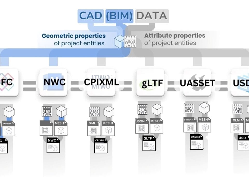
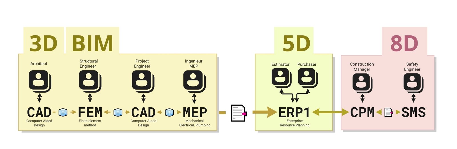
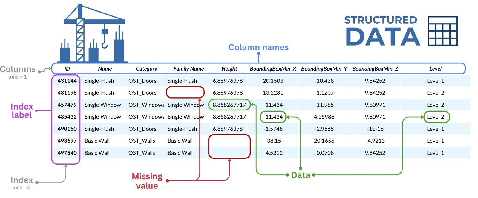
If metadata about project elements are almost always stored in the form of tables, structured or weakly structured formats, then geometric data of project elements in most cases are created using special CAD tools (Fig. 3.1-11), allowing to visualize project elements in detail as a set of lines (2D) or geometric bodies (3D).

When working with geometric data in construction and architecture, three main applications of geometric data can be distinguished (Fig. 3.1-12):
- Confirmation of volumes: geometric data, generated within CAD programs (BIM) using special geometric kernels, are required to automatically and accurately determine the volumes and dimensions of project elements. This data includes automatically calculated areas, volumes, lengths and other important attributes required for planning, budgeting and ordering of resources and materials
- Visualization of the project: in case of any changes in the project, visualization of elements allows to automatically generate updated drawings in different planes. Visualization of the project at the initial stages allows to accelerate the mutual understanding between all participants to save time and resources during the construction process.
- Checking collisions: In complex construction and engineering projects where the interaction of multiple categories of elements (e.g. pipes and walls) without “geometric conflicts” is critical, collision checking plays a key role. Utilizing collision detection software allows you to proactively identify potential geometric conflicts between project elements, preventing costly errors during the construction process.
From the very beginning of engineering and design bureaus, from the time of construction of the first complex structures, structural engineers have provided geometric information in the form of drawings, lines and flat geometric elements (on papyrus, “A0” paperboard or in DWG, PDF, PLT formats), on the basis of which foremen and estimators (Fig. 3.1-11), for the last millennia, with the help of rulers and transportation, collected attributive volumes or quantities of elements and groups of elements.

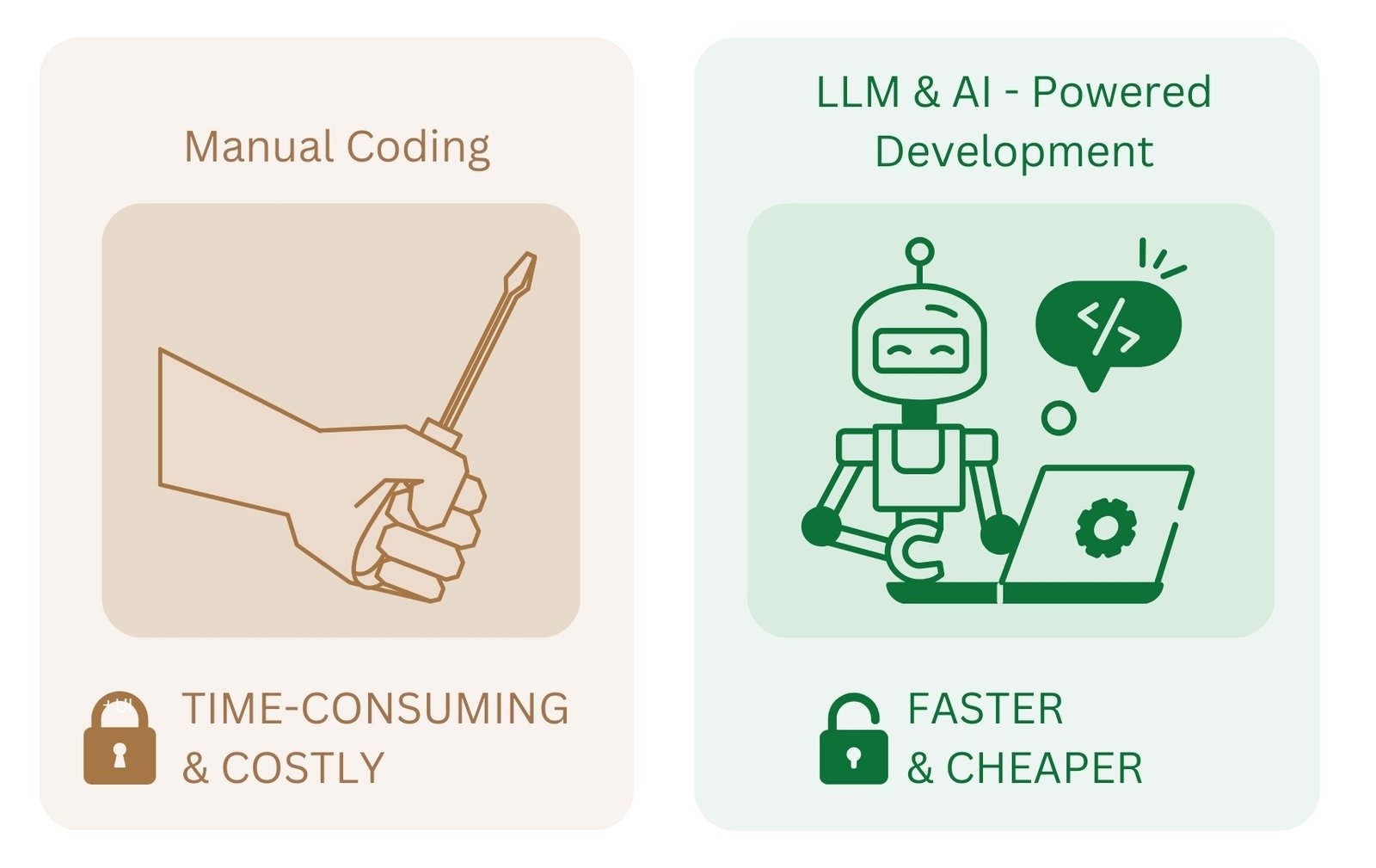
Today, this manual and time-consuming task is solved by full automation thanks to the emergence of volumetric modeling in modern CAD tools (BIM), which allows automatically, with the help of a special geometric kernel, to obtain volumetric attributes of any element without the need to calculate volumetric parameters manually.
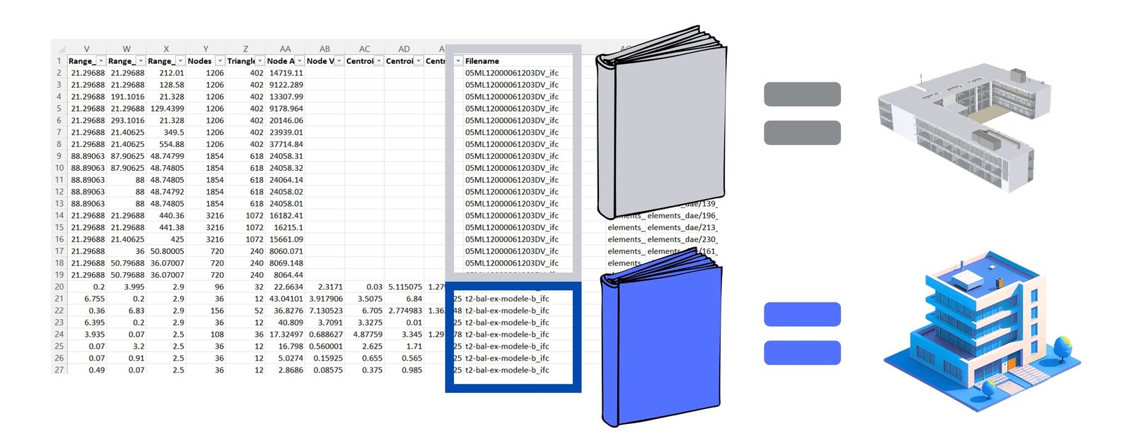
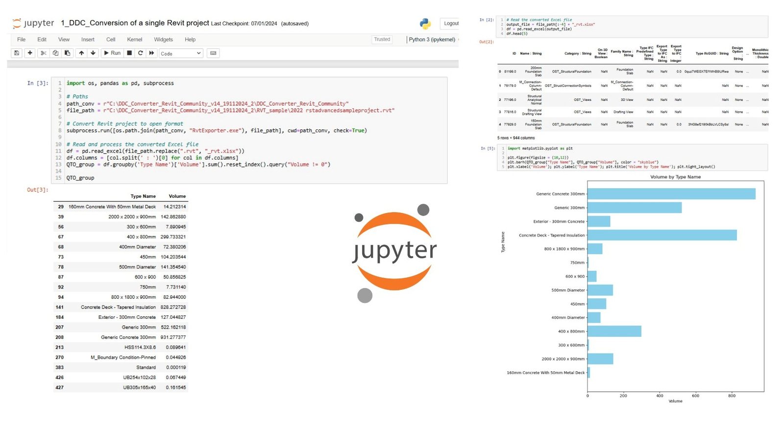
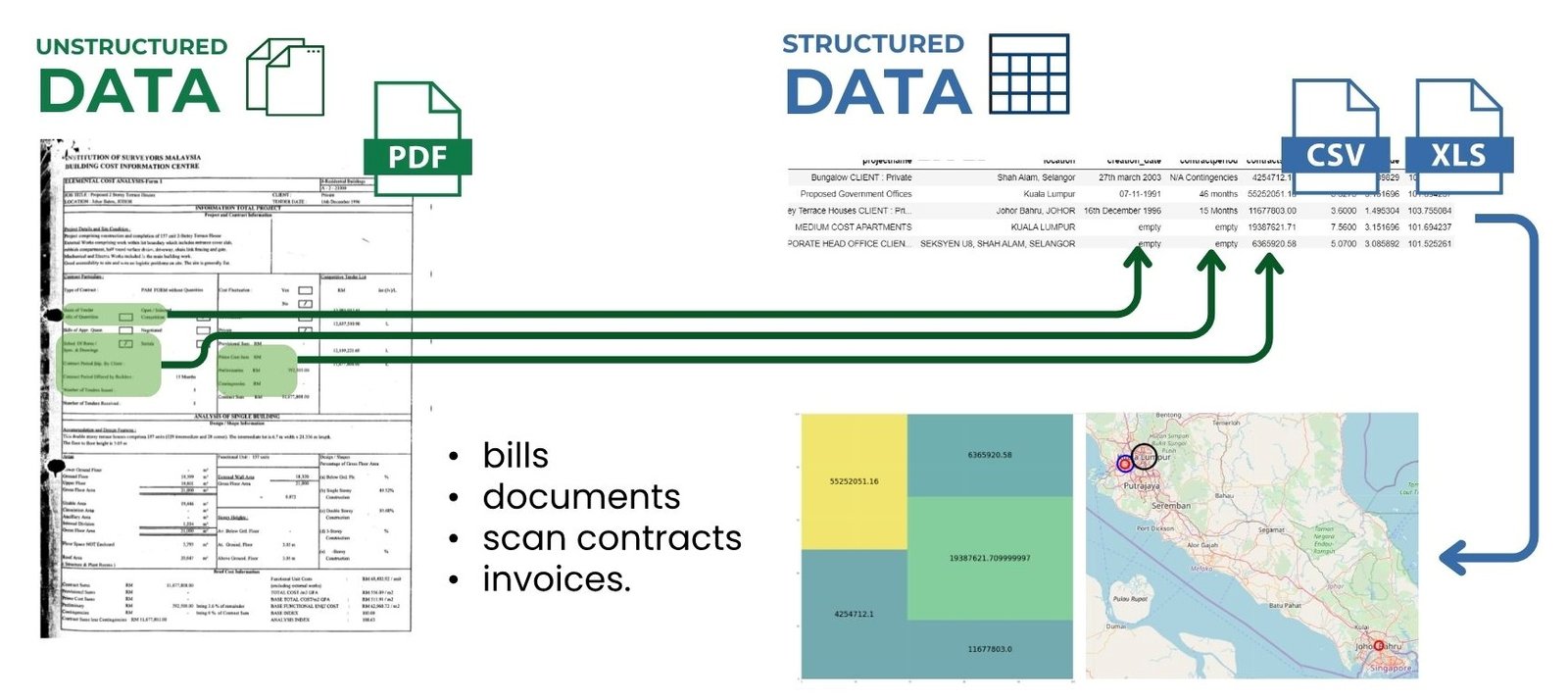
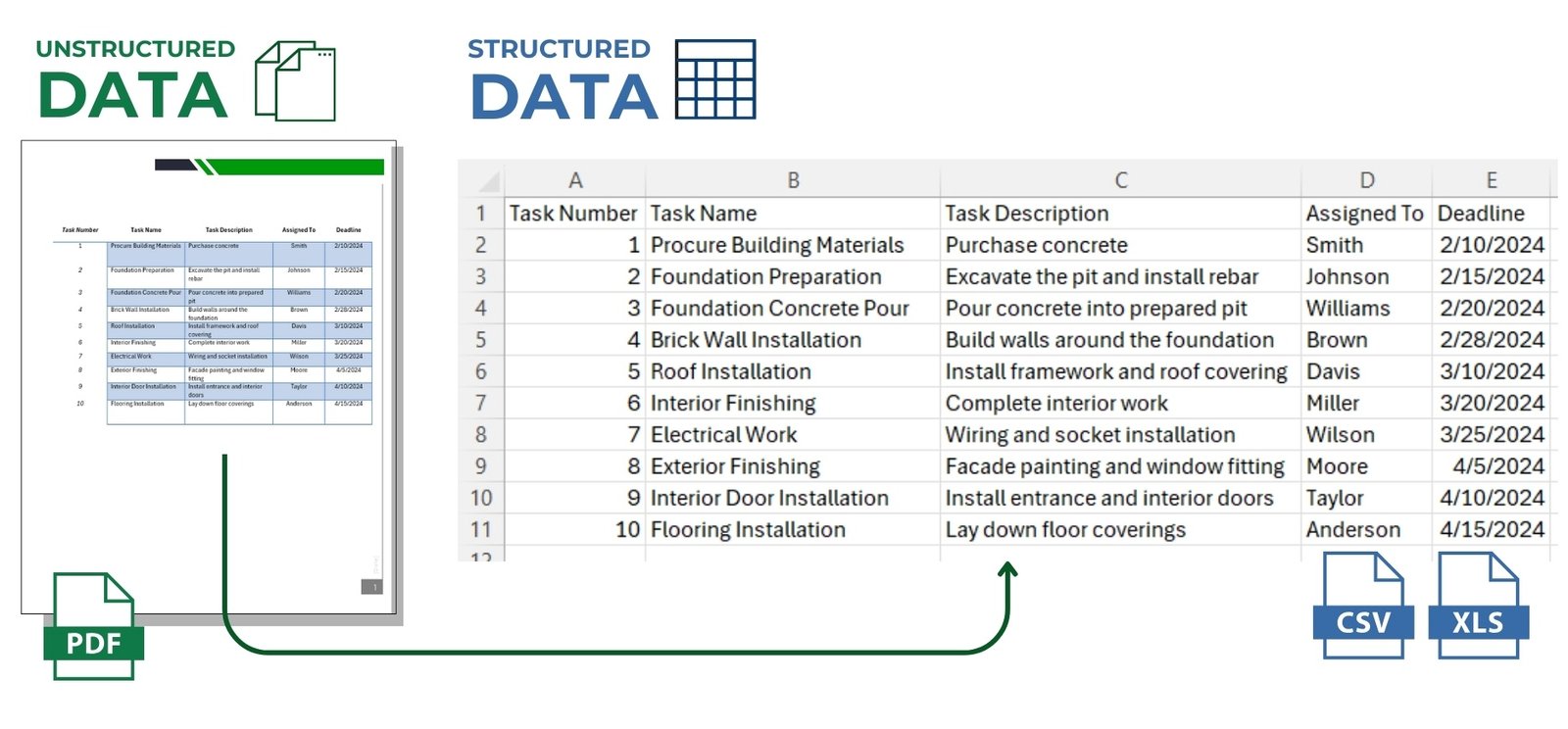
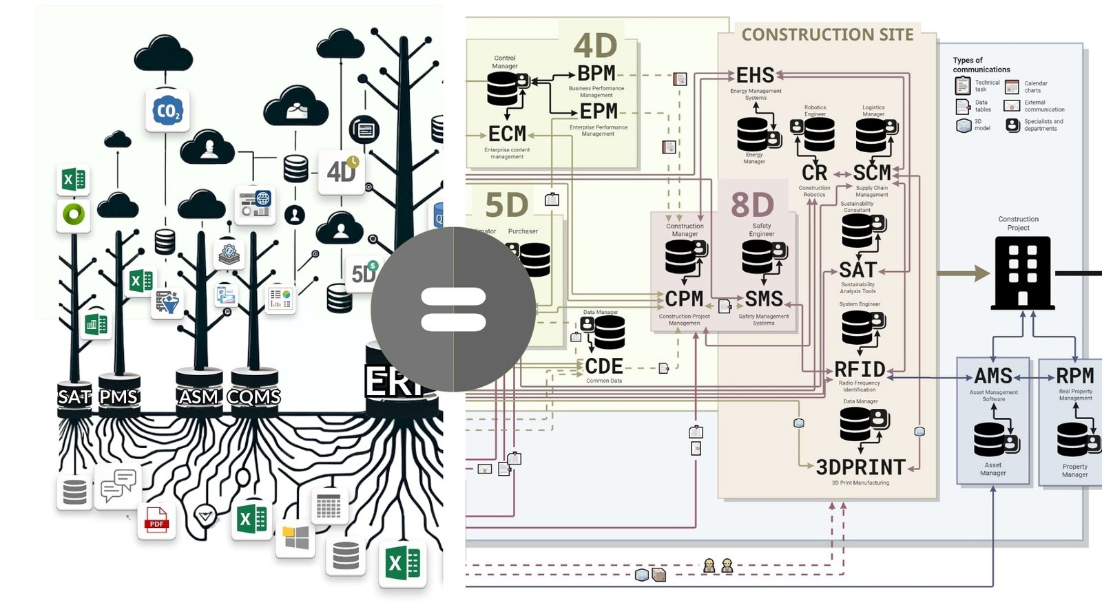
Modern CAD tools also allow you to classify and categorize project elements so that specification tables can be downloaded from the project database for use in various systems, such as cost estimating, scheduling, or CO2 calculation (Fig. 3.1-13). We will discuss Obtaining specifications, QTO tables and quantities, and practical examples in the chapter “Obtaining quantities and quantification”.

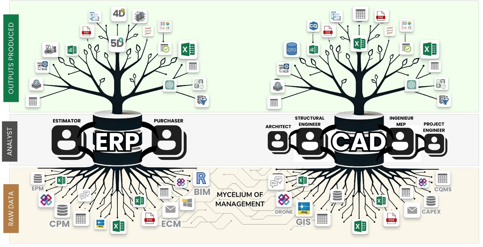
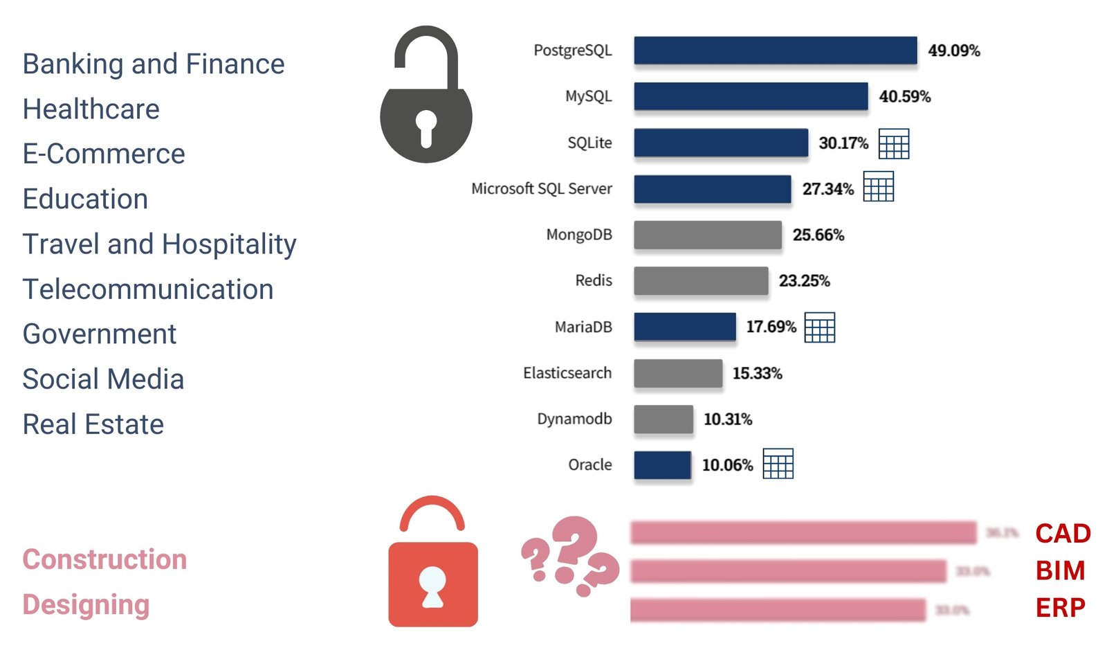
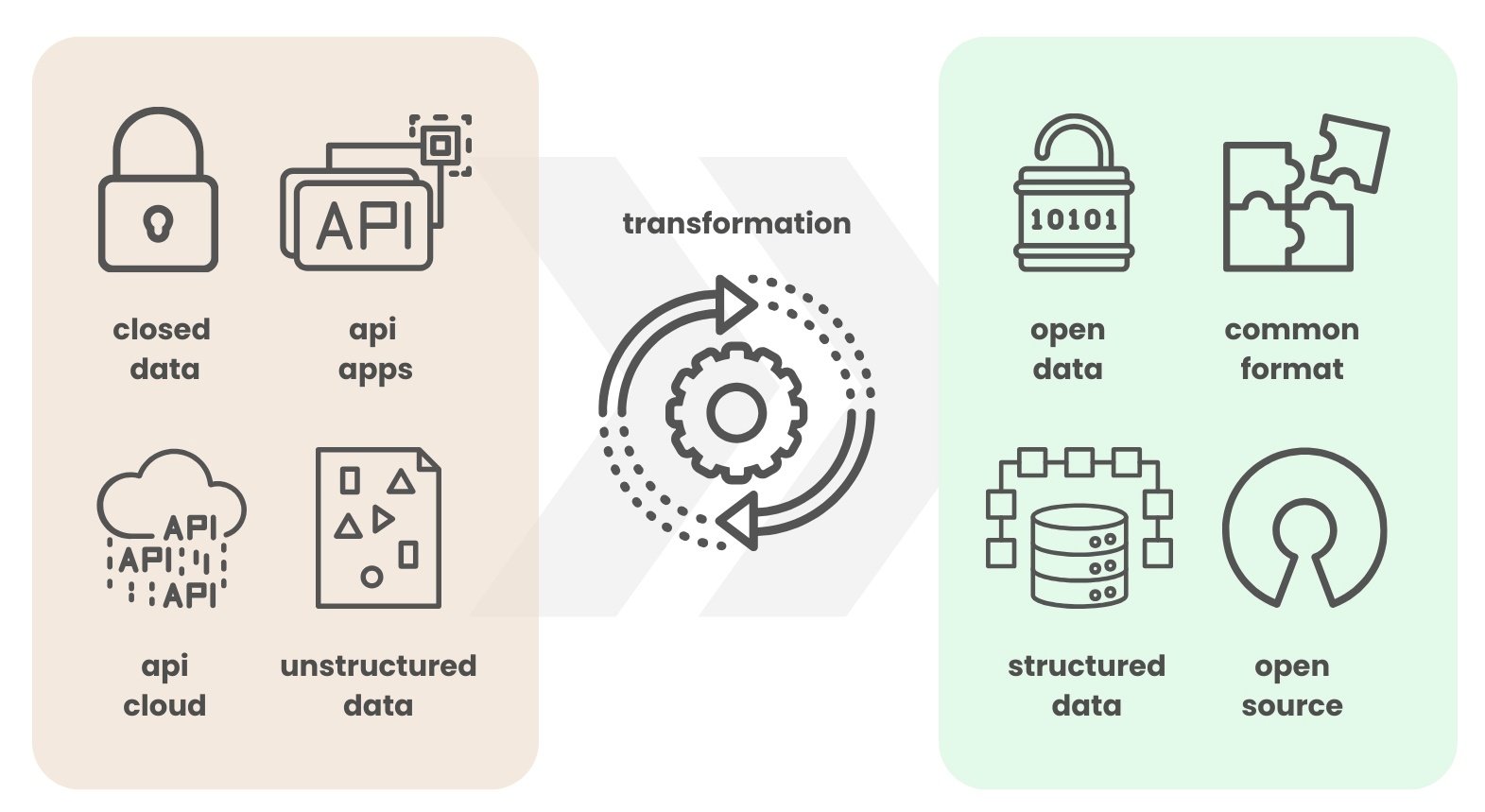
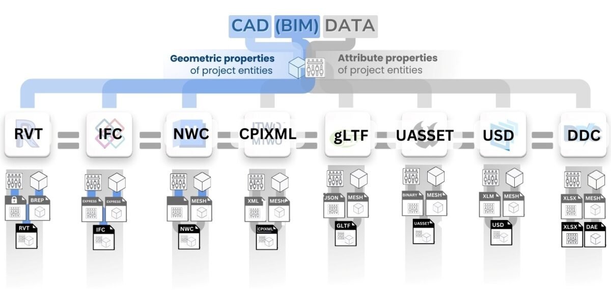
Due to the closed nature of databases and formats used in CAD environment, geometric data created in CAD solutions have actually become a separate type of information. It combines both geometry of elements and meta-information (structured or semi-structured), enclosed in specialized files and formats.


