
In addition to geometric representation formats, in a world where different industries use different levels of detail and depth of data, CAD – (BIM-) methodologies offer their own unique classification systems, which structure the approach to informing building models.
One of the examples of new approaches to standardization is the introduction of levels of model development, reflecting the degree of readiness and reliability of both graphical and information components. For differentiation of information content in work with CAD – (BIM-) data there appeared LOD (Level Of Detail) – level of detail of the graphical part of the model, and LOI (Level Of Information) – level of data elaboration. In addition, for the integrated approach the concept of LOA (Level of Accuracy) was introduced – the accuracy of represented elements and LOG (Level of Geometry) to determine the accuracy of graphical representation.
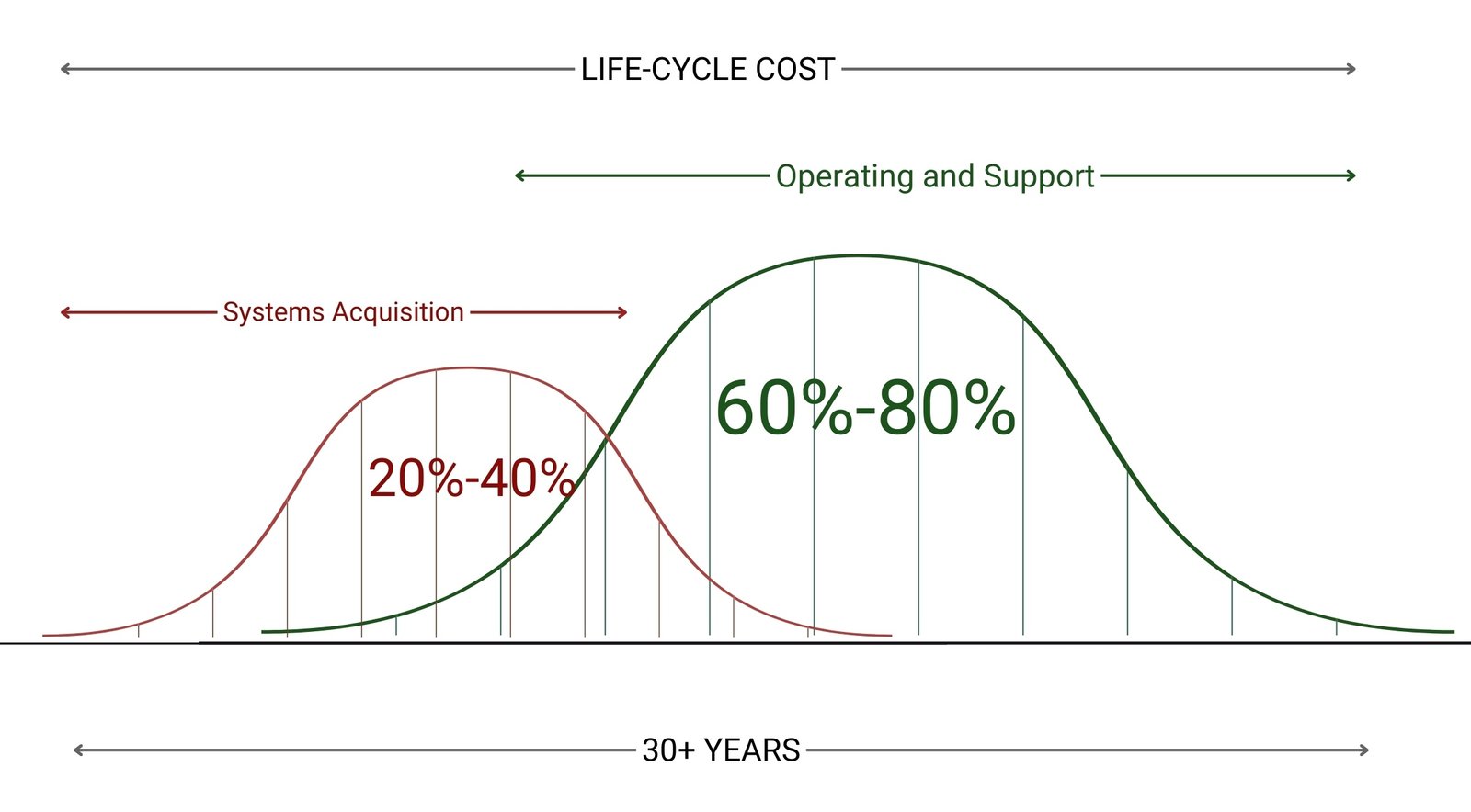
Levels of detail (LOD) are indicated by numbers from 100 to 500, reflecting the degree of model development. LOD 100 is a conceptual model with general shapes and dimensions. LOD 200 includes more precise dimensions and shapes, but with conditional detail. LOD 300 is a detailed model with precise dimensions, shapes, and element locations. LOD 400 contains detailed information required for fabrication and installation of elements. LOD 500 reflects the actual condition of the facility after construction and is used for operation and maintenance. These levels describe the structure of CAD (BIM) model information saturation at different stages of the life cycle, including 3D, 4D, 5D and beyond.
In real projects, high level of detail (LOD400) is often excessive and it is sufficient to use LOD100 geometry or even flat drawings, while the rest of the data can be obtained either by calculation or from related elements that may not have a distinct geometry. For example, spaces and room elements (categories of “Premises” elements) may have no visual geometry, but still contain significant amounts of information and databases around which many business processes are built.
Therefore, it is important to clearly define the required level of detail before starting the design. For 4D -7D use cases, even DWG drawings and minimal LOD100 geometry are often sufficient. The key task in the requirements process is to find a balance between saturation and practical applicability of the model.
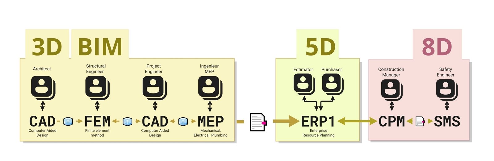
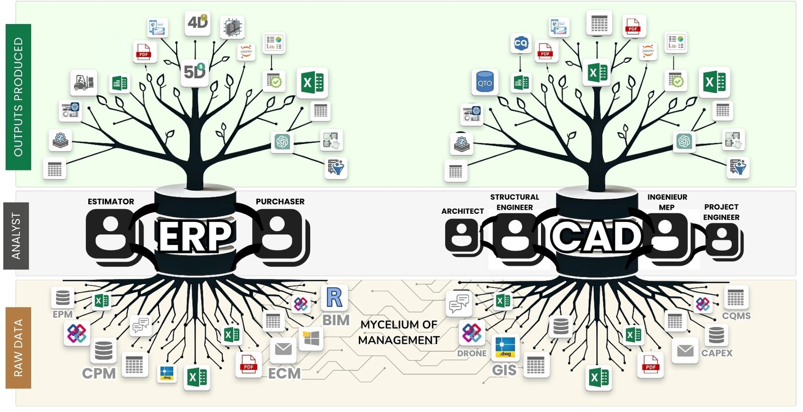
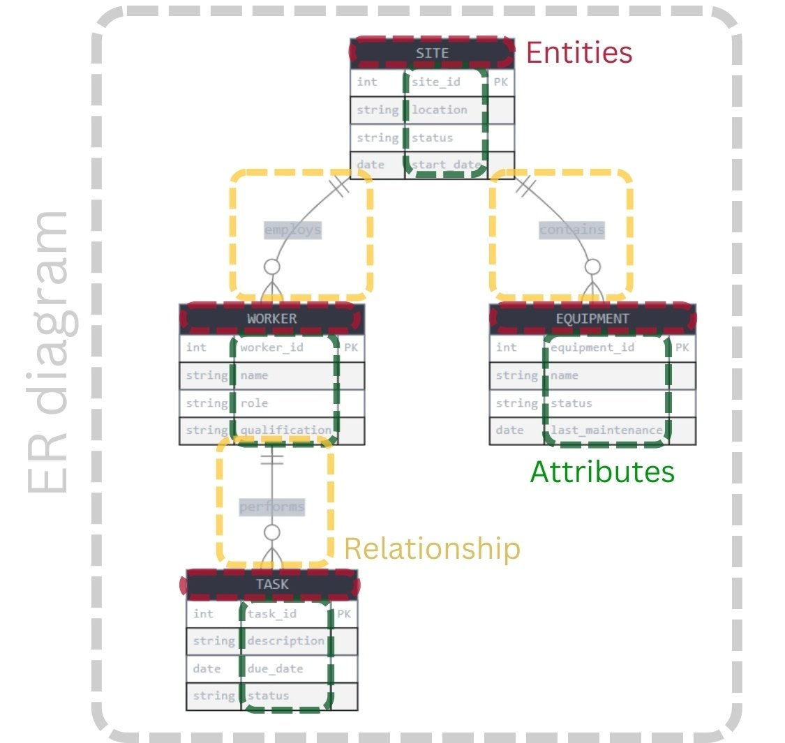
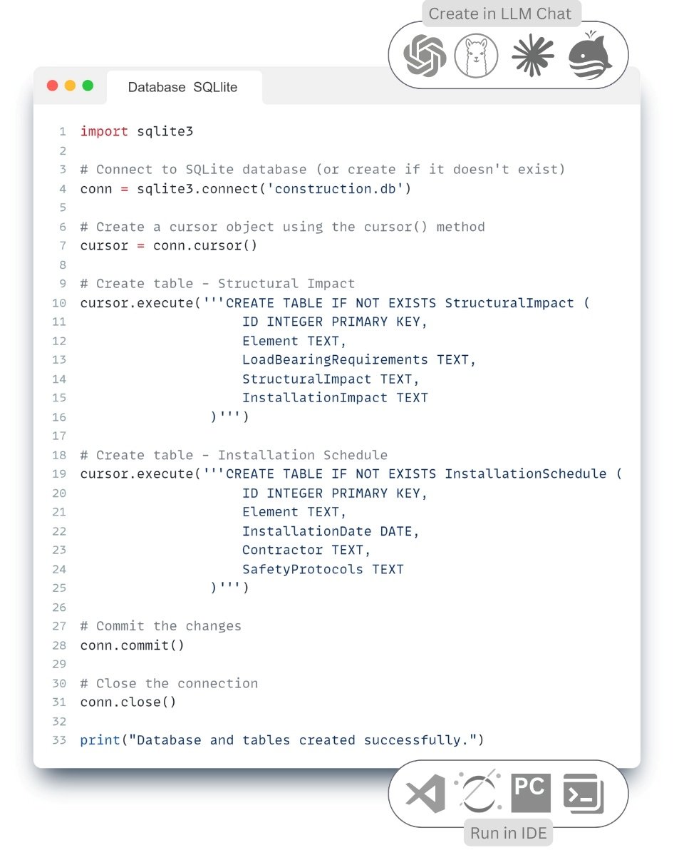
In essence, if we consider CAD (BIM) data as a database (which it is), the description of model saturation through new acronyms is nothing but a step-by-step modeling of data for information systems, starting from the conceptual level and ending with the physical one (Fig. 6.3-4), which was discussed in detail in the third and fourth parts of the book. Each increase of LOD and LOI means addition of information needed for new tasks: calculations, construction management, operation and is characterized by successive enrichment of the model with additional information layers (3D -8D) in the form of various parameters, which we discussed in the fifth part of the book.
")
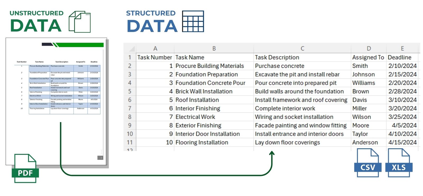
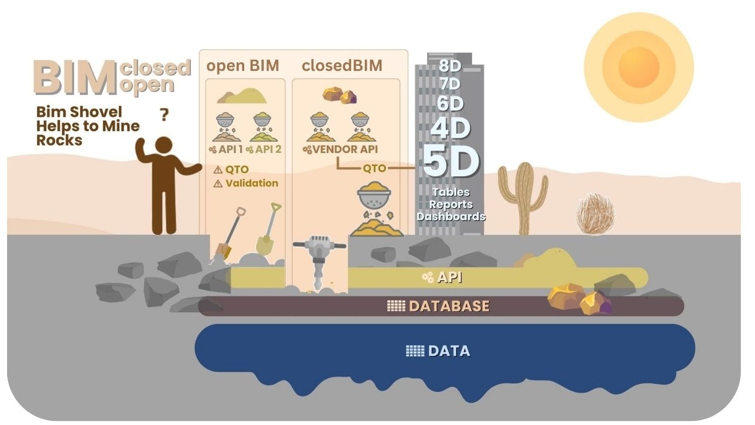
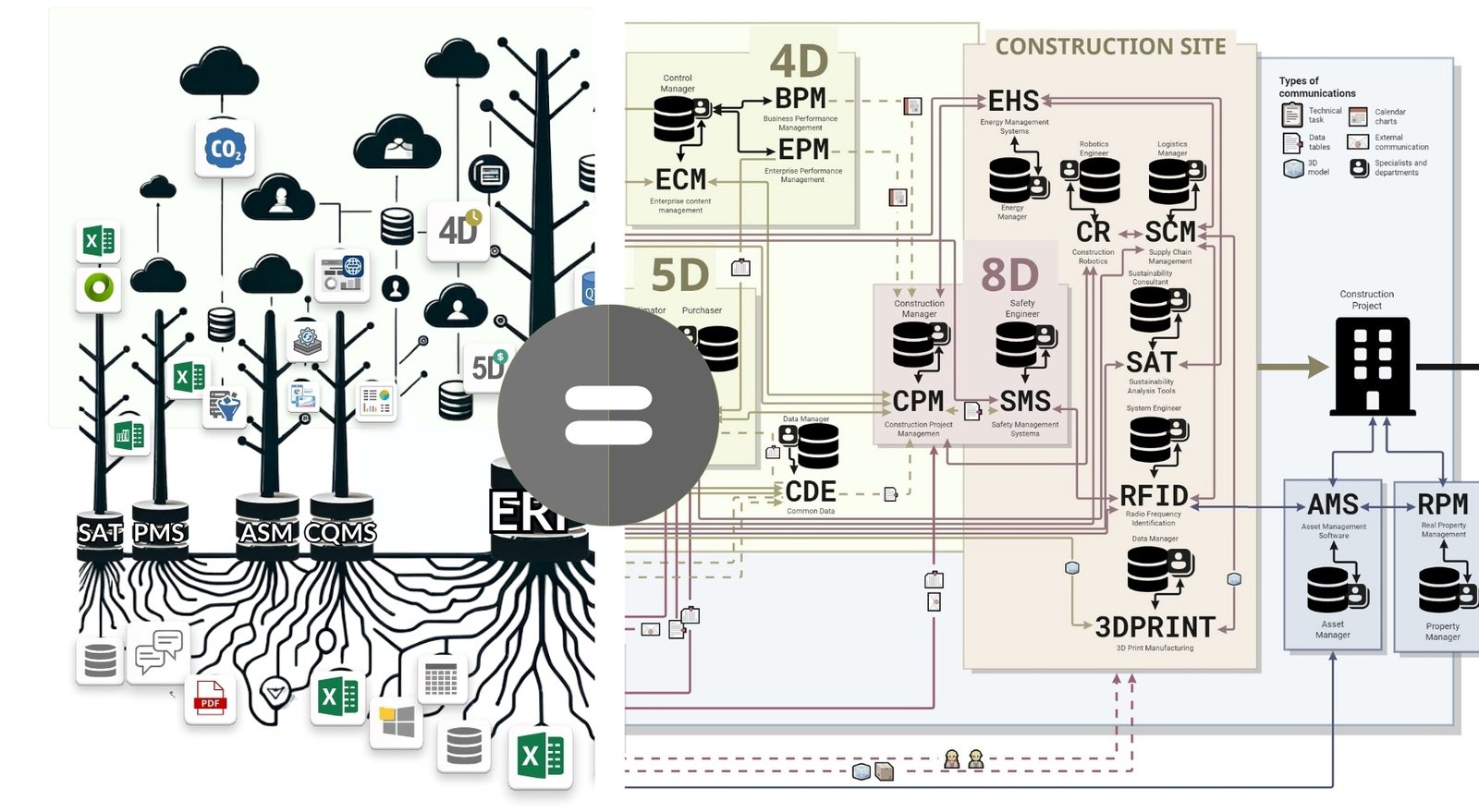
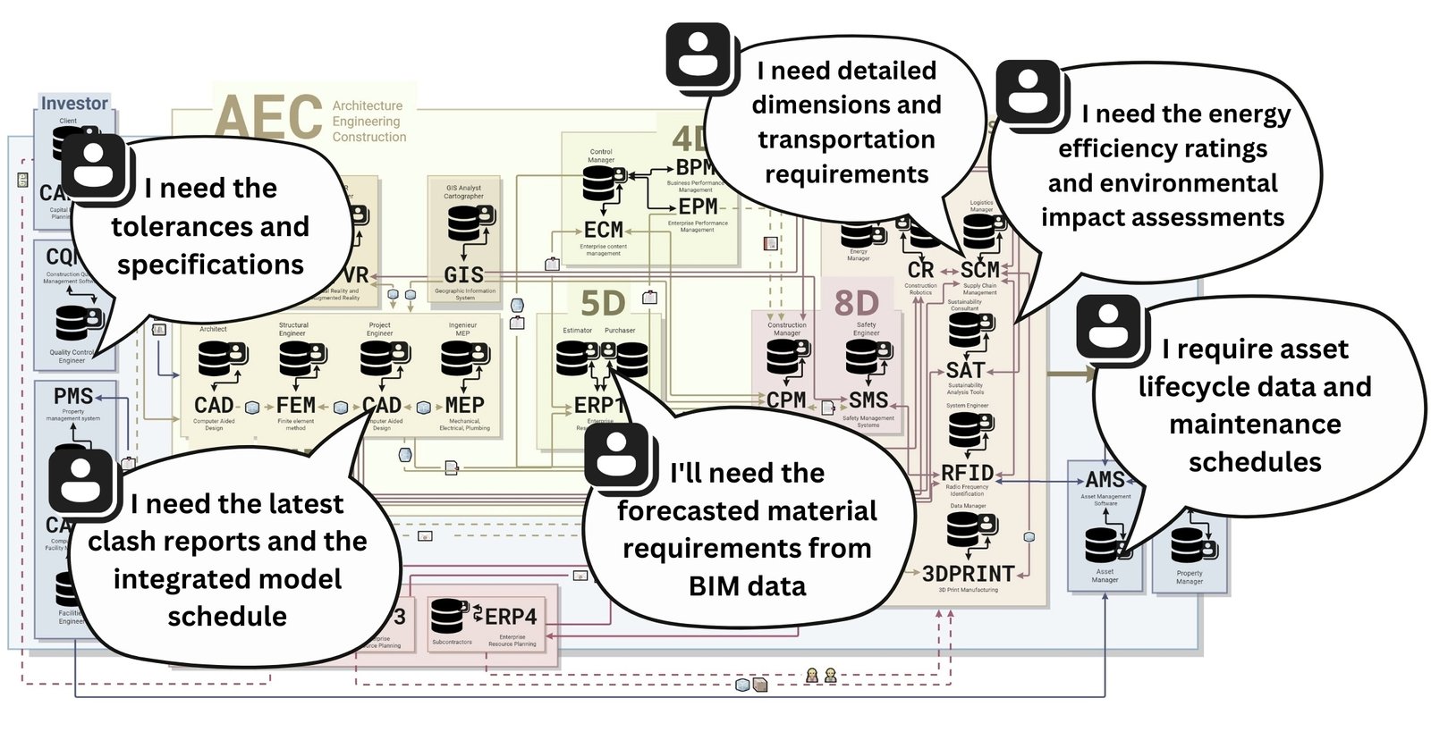
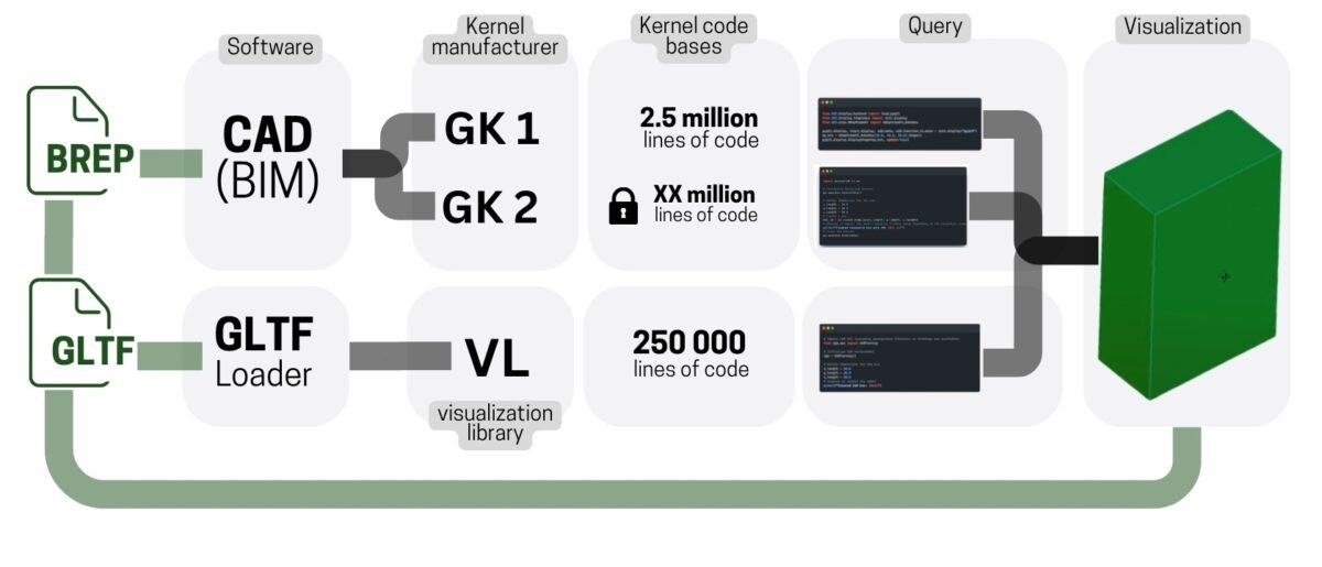
Geometry is only some of the design data, the need for which is not always justified in construction projects and the key issue of working with CAD -data is not so much how the models are visualized, but more how the data from these models can be used outside of CAD- (BIM -) programs.
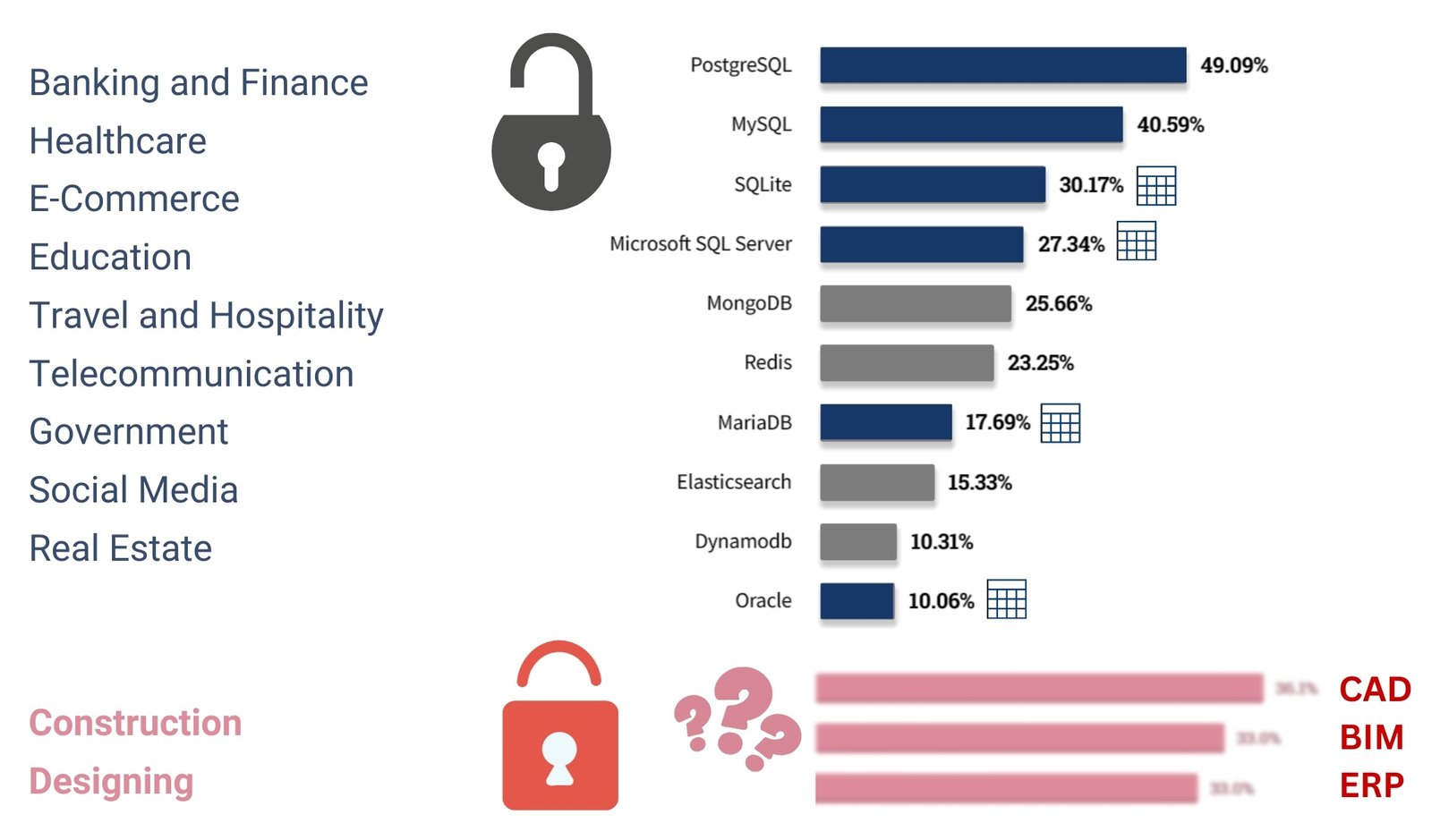
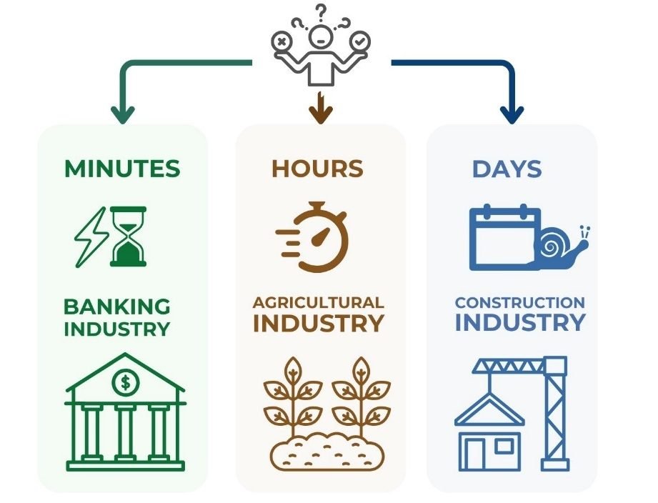
By the mid-2000s, the construction industry faced an unprecedented challenge with the rapid increase in the amount of data in management and data processing systems, especially those coming from CAD departments (BIM). This dramatic increase in data volume took company managers by surprise and they were unprepared for the growing demands on data quality and management.


