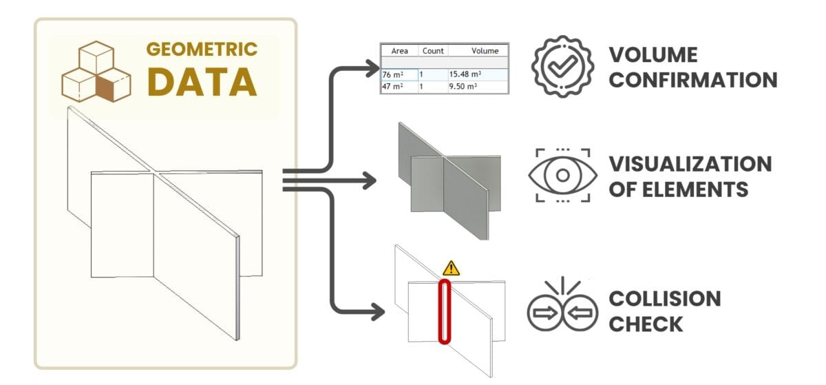
If meta-information about project elements is stored almost always in the form of tables and structured data, then geometric data of project elements in most cases are created using special 2D and 3D CAD (BIM) tools that allow to visualize the project elements in detail as a set of lines (2D) or geometric bodies (3D).
In working with geometric data in construction and architecture, three key areas of application for geometric CAD (BIM) data can be identified:
- Confirmation of Volumes: Geometric data generated by CAD (BIM) programs is critical to automatically and accurately determine the volumes and dimensions of elements in a project. This data includes automatically calculated areas, volumes, lengths and other important attributes needed for planning, budgeting and ordering resources and materials.
- Project Visualization: Visualization of project elements in 3D makes it possible, in case of any changes in the project, to automatically generate updated drawings in various planes. Visualization of the project at the initial stages allows to accelerate mutual understanding between all participants, saving valuable time and resources during construction.
- Collision checking: In complex construction and engineering projects where the interaction of multiple elements (e.g. pipes and walls) without "geometric conflicts" is critical, collision checking plays a key role. Utilizing collision detection software allows to proactively detect potential geometric conflicts between project elements, preventing costly errors during the construction process.

One of the key purposes of creating geometry is to confirm element volumes, which later in other systems are expressed in terms of the cost and time of groups of entities of elements
From the very beginning of appearance of engineering and design bureaus, design engineers provided geometric information in the form of drawings of lines and flat geometric elements (in papyrus, A0 watman or formats, DWG, PDF, PLT), on the basis of which foremen and estimators, for the last thousands of years, with the help of rulers and conveyors collected attribute volumes or the number of elements (entities).
This manual and time-consuming task is now solved by full automation thanks to the advent of volumetric modelling in modern CAD tools (BIM), which now allows to automatically obtain the volumetric attributes of any element, without having to calculate these values manually on a calculator.
“We need to be able to manage all that data (CAD (BIM) project data - Author's note), store it digitally and sell lifecycle and process management software, because for every engineer who creates something (in (CAD (BIM) - Author's note), there are ten people who work with that data”.
Interview C.B. CEO Autodesk®, 2005
Modern CAD (BIM) tools provide project elements not only with precise geometry: shape and dimensions, but also allow to automatically create from these geometries tables of specifications for volumes, which are later used in ERP systems at the stages of calculations, scheduling or e.g. calculation of CO2 emissions. We will talk more about the topic of obtaining specifications, QTO and volume tables and practical cases in the chapter "Obtaining Volumes and Quantity Take-Off".

Most CAD (BIM) tools use databases to store data. Engineers have to transfer data from these databases to various management tools for further use
In addition to volumetric modelling of elements in CAD (BIM) tools, there is an additional information layer due to the BOM concept from mechanical engineering, which CAD (BIM) vendors vendors have labelled with special marketing acronym BIM (Building Information Modeling) - an acronym that has been actively promoted since 2003.
Thanks to the efforts of CAD (BIM) suppliers, data created in CAD (BIM) solutions has become a separate, as if existing, new type of BIM data combining both geometric information about elements and meta-information, collected in special CAD (BIM) format.


